Whether you’ve already purchased Carl's Pro Golf Simulator Enclosure Kit or you’re still trying to decide if it’s the right fit for you, this guide covers everything you need to know about putting together Carl's Pro Enclosures.
Carl’s Pro Enclosure Assembly
Watch our step-by-step video of how to assemble Carl's Pro Golf Simulator Enclosure Kit start to finish.
Looking for assembly instructions for a previous version?
2024 - 2025 Pro Enclosures |
2023 - 2024 Pro Enclosures |
2021 - 2023 Pro Enclosures |
2020 - 2021 Pro Enclosures |
More Helpful Assembly Resources
Build Your Top Golf Simulator Using 2-inch EMT

Our Pro Golf Simulator Enclosure Kits are designed for high-end golf simulator installations. However, it is important to know that it’s not always about what you see that can make or break your golf simulator enclosure. This is why Carl’s Place provides all necessary components and recommends using structural tubing in the form of 2-inch Electrical Metallic Tubing/Conduit (EMT) to build our Pro Enclosures.
Carl’s Place offers the option of precut and marked 2-inch EMT with any Pro Enclosure purchase.
|
|
WHERE CAN I FIND 2-INCH EMT?
If the customer would rather buy and cut their own 2-inch EMT instead of having it shipped from Carl’s Place, check in with your local hardware store or big-box store.
Included in your Carl’s Place Pro Golf Enclosure Kit will be details on what lengths and quantities of EMT are required. Most hardware stores have 2-inch EMT available in 10-foot sections, and some stores will even cut the EMT down to the sizes that you need. If you want to cut the EMT to size at home, we suggest using a sawzall style saw or a standard chop saw.
Be sure to make safety your top priority. Wear proper eye and ear protection when using any cutting tools, and in order to avoid cuts to your hands and make assembly easier, we suggest using a file and deburring tool to smooth out the pipe edges after cutting. The diagram in the kit will help you mark and assemble your frame.

WHY EMT?
Our customer service team at Carl’s Place answers many questions about other options for the framing of a golf simulator enclosure. We suggest using EMT to create a frame that can bear weight and a structure that will support electronics, projector mounts and other accessories.
We don’t suggest using PVC piping because it can be flexible at times, causing sagging and fitting issues. Sagging causes the side walls to not stay taut and could have a “stage curtain effect,” meaning the screen might not hang flat because the vertical and horizontal pipes begin to bow.
Also, the fittings of the Carl’s Place Pro Enclosure are specially designed to be used with 2-inch EMT and not 2-inch PVC pipes as the different types of pipes are slightly different sizes.
Although our DIY Enclosures use 1-inch EMT, we do not suggest using that for our Pro Enclosures as the smaller piping cannot support the same amount of weight. The 2-inch EMT has thicker side walls and is more rigid, allowing it to span wider distances than the 1-inch. Also, the 1-inch EMT cannot bear the weight of an overhead launch monitor or mounted projector.
Carl’s Place Pro Enclosures use the 2-inch EMT to build wider and deeper enclosures without having to brace the longer lengths with vertical supports.
We rarely, if ever, hear of any damage to EMT from errant shots due to the overall strength of the EMT, but also because our Pro Enclosures have optional padding that protects the piping from ball strikes. The padding also protects the player(s) by keeping balls from ricocheting back at them off the piping.
Wondering how to connect your 2-inch EMT at the corners of your Pro Enclosure? Carl’s Place offers 2-inch steel fittings for piping connections and corners.
KEEP IN MIND
When looking at a Pro Enclosure, the actual outer dimensions of the 2-inch EMT frame will be roughly 5 inches larger than the listing size. For instance, if you are looking at the 90 inches tall by 156 inches wide (16:9 aspect ratio) set up, the actual outer dimensions of the enclosure would be 95 inches tall by 160.5 inches wide.
Orders with a 'Pipe Framing Kit' ship freight. You or the recipient needs to be present at the time of delivery and assume responsibility for unloading the pallet or be responsible for any charges incurred at the time of delivery. The heaviest box is likely to weigh about 50 pounds. Customers who are unable to unload the pallet box-by-box should add lift gate service. Price is an estimate that is valid to most locations.
For more information on each enclosure size, please reference the specifications tab underneath the pricing information on our Pro Enclosure web page.

Video Transcript
Please note, this transcript is for reference only. For complete guidance on assembling your PRO Golf Simulator Enclosure Kit, please read the Assembly Manual.
---
At Carl’s Place, our Golf Simulator Enclosures are designed to be user-friendly and easy to assemble. In this video, we will walk you through the setup process for our PRO golf Enclosure Kit, (as well as provide you with some tips and tricks that help along the way.)
What's in the box
You’ll want to start by organizing your frame kit by size and shape. Your Pro kit will include:
- Bag with Literature and Hardware
- Fabric enclosure cover
- (5) Detached flaps
- Impact screen with cable
- (2) Cable receivers
- (2) Springs
- Zip ties
- Foam inserts
- Kit of pre-cut and marked pipes OR self-sourced, if pipes were not purchased
- Fittings to connect the pipes
You can order optional add ons for your kit, such as: a pipe framing kit, crossbar, ceiling baffles, and a back cover kit. If you purchased a back cover or crossbar kit, you’ll receive additional fittings, pipes and instructions to complete that assembly. If you purchased your Pro kit without the optional pipe framing included, you’ll need to purchase the EMT from a local hardware store and cut it to size. Detailed assembly instructions are also included to help guide you step-by-step in the assembly process.
Tools needed
Make sure to have your tools handy - You’ll need at least one (6mm and 3/16” hex bit ratchet or key), a measuring tape, a rubber mallet, pliers, a cutting tool, at least one 8 foot tall step ladder ,and we’d recommend having a friend to help.
Assemble the Frame
Once you have your workspace prepped, it’s time to assemble your frame. Be sure to reference your specific Frame Assembly Sheet included with your kit, that details the dimensions to the specific sized kit that you ordered.
Before you start assembling the frame, make sure that your fitting screws are loose, so that you can insert the EMT pipes without interference.
Begin assembling your frame by connecting any of the straight fittings or connection fittings, to the appropriate EMT pipes marked on your cut sheet.
Take note that the pipe is inserted all the way into the fittings. You can use a rubber mallet to make sure the pipes are completely inserted. Tighten the fittings to the EMT using a 6mm hex bit. wrench.
Start by building the frame from the floor up, working from the back of the enclosure to the front. Take one of your assembled width pipes and two of your depth pipes and lay them out in a U - shape on the floor. (It can help to Organize your pipes in position on the floor where they will end up in the assembly.) Your two included “L” fittings will be assembled at the front of the enclosure, with the “cable fittings” at the rear.
Next insert the EMT pipes for your height. Put the “three way connection fittings with the nub” (top rear fittings) on the top of each rear height pipe with the nub facing the rear of the enclosure.
When assembling the top-half of the frame, it’s important to work from the back of the enclosure to the front. Point the bolts on all C fittings to face toward the rear of the enclosure.
(show width and depth pipes being inserted with F3 fittings on the front of enclosure)
Double check that all fitting screws are tightened down and complete the frame assembly by measuring the frame to make sure that all dimensions match the dimensions specified in your diagram.
Hang Enclosure Cover
The next step is to hang and attach your fabric enclosure cover.
For easiest installation, bring the cover to the left side of the enclosure. Partially unfold the cover just enough to match the depth of your enclosure. Make sure the grommeted edge is in line with the rear of your enclosure, and then lift it up and over the top of the frame. Pull the cover until it is even on both sides of the frame.
Once the cover is over the frame, confirm that:
- The grommeted edges are toward the back of the frame.
- The thicker hook-and-loop strips along the grommets face the inside of the enclosure
- The skinnier hook-and-loop stips along the grommets face the outside of the enclosure)
To attach the top flaps, add one zip tie to each top corner of the enclosure to add tension, then attach the top flap around the front enclosure pipe, starting at the center and working outwards. You’ll want to try and make the connection as smooth and neat as you can at this time, because it’ll minimize the wrinkles in the enclosure cover later on.
Now attach your side flaps around the front pipe to the hook and loop strip, ( the corner flaps can wait for now. )
Make sure to go over and smooth down any edges. (It’s easier to make adjustments now versus after you pull the fabric taut with zip ties.)
If you have excess material in the front corners, you can tuck it under the enclosure frame for a cleaner look.
Finish by securing the grommeted edge to the frame with zipties. Tighten the zipties just until taught, so that they aren’t stretching the enclosure cover in any areas. Use a single ziptie through the bottom two grommets on the bottom of the frame. Check to make sure that the tension of the enclosure is evenly spaced from the rear of the frame.
Install (Optional) Baffles
If you have baffles included with your kit you can install them now.
Hang the baffle(s) with zip ties around the top pipes on each side of the enclosure, with the matte side facing the front.
Baffles can be spaced at any preferred distance away from the screen. 1 - 1.5 ft apart is common.
Attach the Impact screen
Now that your enclosure cover is complete, it’s time to attach your impact screen to the frame. Be careful unfolding your screen to keep it from touching the floor and becoming dirty. The front of the screen should be oriented with the Carl’s Place logo at the top left of the enclosure.
Loosely hang the screen on the frame, beginning with two zip ties in each of the top two corners; one connecting in each direction. Continue loosely securing the rest of the zip ties across the top of the screen only. DO NOT overtighten zip ties. Zip ties should not stretch the screen but just hold it flat. Tighten only until they just start to pull on the screen.
Next, you’ll attach the bottom of the impact screen using the cable. The cable is pre-threaded through the bottom sleeve of the impact screen.
On one of the rear corner fittings, locate the small hole at the base of the fitting.
On one bottom side of the screen, insert the cable through the fitting. Take a cable receiver and spring and slide the spring over the cable receiver. Then, thread the receiver with the spring onto the end of the cable, with at least 4 full turns of the cable receiver. Repeat this process on the other side.
Alternate tightening each end of the cable. Use a pliers to hold the cable and prevent it from spinning, while using 3/16” Hex key to tighten the receiver. DO NOT OVERTIGHTEN.
Tighten until the springs compress and the receivers stick out ⅞”.
Return to the top zip ties.
Starting with the corners, carefully tighten each zip tie until the screen barely touches (and is level with) the floor.
Add zip ties to all remaining grommets on the sides of the screen.
Zip ties should not stretch the screen. Tighten until barely taut.
Secure each of the bottom grommets of the screen with a zip tie. Wrap the zip tie under and around the bottom pipe, held in place by the receiver end.
These 2 bottom zip ties can be pulled tight.
Check the screen tension.
The bottom of the screen should be level with the floor and not pulling up in any areas. If there is any tension, replace any overtightened zip ties on the top and sides of the screen to make any corrections.
Crossbar Install
If you ordered a crossbar with your Enclosure you can install it now. This is also the ideal time to attach an electronics mount and even set up the launch monitor itself, as it’s often easier to get everything secured on the mount before lifting the crossbar into place.
Begin by connecting your pipes with the connector fitting (You may have multiple connector fittings if you have a wide enclosure). Then wrap the fabric crossbar cover around the pipe and secure with hook and loop fastener strips (Note: A previous version had a sleeve that slid onto the crossbar). Next, place a crossbar fitting on each top depth pipe of the frame and then raise the crossbar up and slide it into the fittings. Adjust the crossbar placement as needed and tighten the fittings into place.
Attach Flaps and Install Foam Inserts
Now it's time to attach the 5 flaps that will cover the exposed pipes. First, identify each flap. Flap length varies by enclosure size.
- The two depth flaps will be the skinniest of the flaps
- The width flap spans the width of your screen, and has intersecting hook-and-loop strips on one side
- The Height flaps spans the height of your screen, and has a hook fastener strip on each side that runs the length of the flap.
Attach Depth Flaps
Start by attaching your depth flaps to the enclosure cover. Starting at the front of the enclosure, pull back the front corner, just enough to align the flap. Attach the bottom of the flap to the wall, working your way towards the screen, then lift it up and attach it to the ceiling. Make adjustments to smooth out the flaps and front corner as needed. Finish by re-attaching the front corner to the hook and loop. (If the corner is tight to re-attach, use a twisting motion to pull it into place)
Attach Width Flaps to Screen
Next take the width flap, and attach the corner of the hook and loop on the flap - to the top corner hook and loop on the screen.
Continue attaching along that top edge, with the flap hanging down over the screen.
Next, install your foam inserts behind your flap as you lift the flap up and secure it to the ceiling with the hook and loop strips. We recommend installing the foam starting at the center, with the narrow edge of the foam against the frame. Wrap the flap around the foam to secure it with the hook and loop strips.
Any excess foam at the ends will be used behind the height flaps next.
Attach Height Flaps to Screen
Align the height flap to the top of the width flap and Continue down the length of the screen.
Make sure to try to Maintain consistent velcro contact following from the top to the bottom.
Then fold the flap over and secure to the wall using the hook-and-loop strips.
When installing foam behind the flaps, Trim off any excess at the bottom to keep it even with the floor.
Tuck the remaining flap material at the bottom under the enclosure and under the foam inserts
Review your work and reattach the hook and loop to smooth out any lines as necessary.
Further installation
Your setup is complete - and you can begin using your new PRO golf simulator enclosure
We want to see your new golf setup! Go to www.carlofet.com/share-with-us to send us pics, videos, or reviews of your brag worthy setup!
Thanks for watching this video! If you have any questions or feedback feel free to shoot us an email, give us a call, or contact us on our website. Be sure to subscribe to our channel for more videos on building, using, and enhancing your own golf simulator enclosure.
Search articles by tag:
How-To PRO Golf EnclosuresRelated Posts
Golf Simulators, Post-Purchase
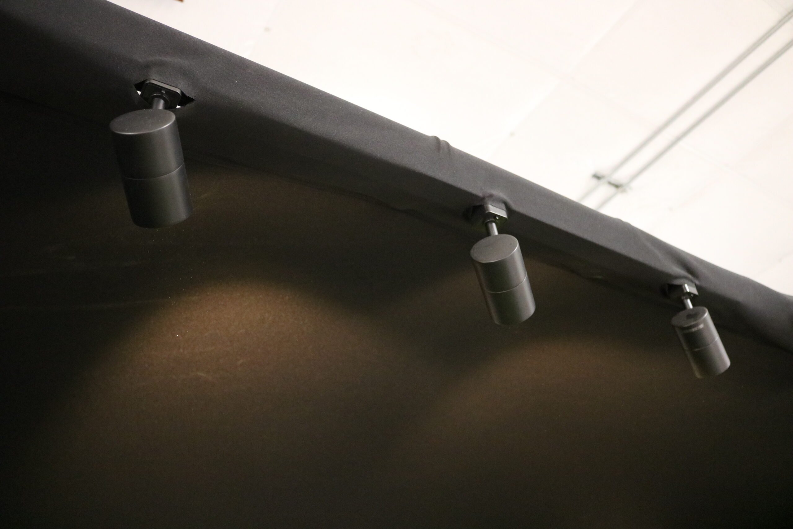
Adding Track-Lighting to your Golf Enclosure
.webp)
Golf Simulators, Computers
Golf Simulator Computers

Golf Simulators
Golf Simulator Lighting: What To Get And Where To Mount Them