Ready to assembly your Carl's DIY Golf Simulator Enclosure? Or maybe you’re just here to check out how simple it is to set up. Either way, you’ve come to the right place!
This guide covers everything you need to know about putting together Carl’s DIY Enclosures. From the tools required to step-by-step instructions. It’s easy, fast, and perfect for creating your own golf space at home.
Carl’s DIY Enclosure Assembly
Watch our step-by-step video of how to assemble Carl's DIY Golf Simulator Enclosure Kit start to finish.
Looking for assembly instructions for a previous version?
2023 - 2025 DIY Enclosures |
2021 - 2023 DIY Enclosures |
2020 - 2021 DIY Enclosures |
|
More Helpful Assembly Resources
HOW TO PURCHASE EMT FOR YOUR DIY KIT
An important thing to know when purchasing a DIY Golf Simulator Enclosure Kit from Carl’s Place is that 1-inch EMT (Electrical Metal Tubing/Conduit) is required to complete these frames. With a DIY Golf Simulator Enclosure Kit you have the option to add on a pipe framing kit with the EMT you need to construct the enclosure. Alternatively, your kit will include all details on what lengths and quantities of EMT are required and you can source them from a local hardware store.
NOTE: 1" EMT is the trade size, but the actual outer diameter is 1.163 inches. If you are sourcing your own pipes, your cut sheet will also note this.
In this quick article, we’ll answer the most common questions about sourcing EMT for your DIY Backyard Theater or DIY Golf Simulator Enclosure Project.
What is 1″ EMT?

Electrical Metal Tubing (EMT) is a zinc-coated steel tube that is primarily used in electrical applications. It is strong and lightweight, making it the perfect material for building your own golf hitting cage or outdoor movie screen. 1″ EMT is what fits perfectly in the fitting connectors that are included with your kit. Other products such as PVC and Rigid tubing are not recommended with our kits.
Where can I find 1″ EMT?

EMT can be found in the electrical section of any local hardware store such as Home Depot or Lowe’s and is typically sold in 10-foot tubes.
How do I cut and mark the 1″ EMT?

Your kit includes instructions for the quantities and lengths of EMT required for the specific design of your project. EMT can be easily cut to length with a sawzall style saw or a standard chop saw. From a safety perspective, please be sure to wear proper eye and ear protection when using any cutting tools.
Safety is key! To prevent cuts to the hand and to make assembly even easier, we recommend using a file and deburring tool to clean up the edges of the pipe once cut. The provided diagram will make it simple to mark and assemble your frame.
1″ EMT is a readily available and inexpensive material that you can easily source for your DIY projector screen project. Consult our resources section for more project tips and ideas.

Video Transcript
Please note, this transcript is for reference only. For complete guidance on assembling your DIY Golf Simulator Enclosure Kit, please read the assembly manual, linked above.
-----
At Carl's Place, our golf simulator enclosures are designed to be userfriendly and easy to assemble. In this video, we will walk you through the setup process for our DIY enclosure kit, as well as provide you with some tips and tricks that help along the way. You'll want to start by organizing your kit by size and shape. Your DIY kit will include a bag with literature and hardware, a fabric enclosure cover, five detached flaps, an impact screen with cable, two cable receivers, zip ties to secure everything to your frame, a kit of pre-cut and marked pipes or self-source pipes if pipes were not purchased. Fittings to hold the pipes. One rear bottom right fitting, one rear bottom left fitting, two rear top fittings, two front bottom fittings, two front top fittings, and seven connector fittings. Optional add-ons for the kit include a pipe framing kit, foam inserts, ceiling baffles, net wall extensions, and a back cover kit. If you purchased a back cover kit, you'll receive additional fittings, pipes, and instructions to complete that assembly. If you purchase your DIY kit without the optional pipe framing included, you'll need to purchase the EMT from a local hardware store and cut it to size. Detailed assembly instructions are also included to help guide you step by step in the assembly process. Make sure to have your tools handy. You'll need at least one/2-in combination wrench or socket wrench, one 3/16 hex key or bit, a measuring tape, a rubber mallet, pliers, a cutting tool, and at least one 8-ft tall stepladder. Once you have your workspace prepped, it's time to assemble your frame. Be sure to reference your specific frame assembly sheet included with your kit that details the dimensions to the specific size kit that you ordered. Before you start assembling the frame, make sure that your fitting screws are loose so that you can insert the EMT pipes without interference.
Begin assembling your frame by connecting any of the straight fittings or connection fittings to the appropriate EMT pipes marked on your cut sheet.
Take note that the pipe is inserted all the way into the fittings. You can use a rubber mallet to make sure the pipes are completely inserted. Tighten the fittings to the EMT using a/2-in wrench. Disregard the holes you see on the pipes. They are part of the manufacturing process and not part of the assembly. Start by building the frame from the floor up, working from the back of the enclosure to the front. Take one of your assembled width pipes and two of your depth pipes and lay them out in a U-shape on the floor. Your two included L fittings will be assembled at the front of the enclosure with the cable fittings at the rear.
Next, insert the EMT pipes for your height.
Put the three-way connection fittings with the nub on the top of each rear pipe pipe with the nub facing the rear of the enclosure.
When assembling the top half of the frame, it's important to work from the back of the enclosure to the front. Point the bolts on all C fittings to face toward the rear of the enclosure.
Double check that all fitting screws are tightened down and complete the frame assembly by measuring the frame to make sure that all dimensions match the dimensions specified in your diagram.
The next step is to hang and attach your fabric enclosure cover. Orient the cover so that the grommeted edges are toward the back of the frame. The front of the panel has a flap that hangs over the front pipe. And the flaps with the hook and loop fasteners face the inside of the enclosure.
Next, attach the bottom flaps. Start by the screen and wrap the enclosure cover under the bottom of the frame and attach it to the side of the enclosure cover using the hook and loop fasteners.
To attach the top flaps, add one zip tie to each top corner of the enclosure to add tension. Then attach the top flap around the front of the enclosure pipe, starting at the center and working outwards. You'll want to try and make the connection as smooth and neat as you can at this time because it'll minimize the wrinkles in the enclosure cover later on. Now, attach your side flaps around the front pipe to the hook and loop strip. The corner flaps can wait for now. Make sure to go over and smooth down any edges. It's easier to make adjustments now versus after you pull the fabric taut with zip ties. If you have excess material in the front corners, you can tuck it under the enclosure frame for a cleaner look. Finish by securing the grommeted edge to the frame with zip ties.
Tighten the zip ties just until taut so that they aren't stretching the enclosure cover in any areas.
Use a single zip tie through the bottom two grommets on the bottom of the frame.
Finally, check to make sure that the tension of the enclosure is evenly spaced from the rear of the frame.
Now that your enclosure cover is complete, it's time to attach your impact screen to the frame. Be careful unfolding your screen to keep it from touching the floor and becoming dirty. The front of the screen should be oriented with the Carl's Place logo at the top left of the enclosure. Loosely hang the screen from the frame, beginning with two zip ties in each of the top two corners, one connecting in each direction.
Continue loosely securing the rest of the zip ties across the top of the screen only. Do not overtighten the zip ties. Zip ties should not stretch the screen, but just hold it flat. Tighten only until they just start to put tension on the screen. Next, you'll attach the bottom of the impact screen using a cable. The cable is prethreaded through the bottom sleeve of the impact screen. On one of the rear corner fittings, locate the small hole at the base of the fitting. Insert the cable through the fitting. Take a cable receiver and spring and slide the spring over the cable receiver. Then thread the receiver with the spring onto the end of the cable with at least four full turns of the cable receiver.
Repeat this process on the other side. Alternate tightening each end of the cable. Use a pliers to hold the cable and prevent it from spinning while using a 3/16 hex key to tighten the receiver. Do not overtighten. Tighten until the spring compresses and the receivers stick out 7/8 of an inch. Return to the top zip ties. Starting with the corners, carefully tighten each zip tie until the screen barely touches and is level with the floor. Add zip ties to all remaining grommets on the sides of the screen. Zip ties should not stretch the screen. Tighten until barely taut.
Secure each of the bottom grommets on the screen with a zip tie. Wrap the zip tie under and around the bottom pipe held in place by the receiver end.
These two bottom zip ties can be pulled tight.
Check the screen tension. The bottom of the screen should be level with the floor and not pulling up in any areas. If there is any tension, replace any overtighten zip ties on the top and sides of the screen to make any corrections. Now that the screen is hanging, it's time to attach the five flaps that will cover the exposed pipes. First, identify each flap. Flap lengths will vary by enclosure size. The two depth flaps will be the skinniest of the flaps. The width flap spans the width of your screen and has intersecting hook and loop strips on one side. The height flap spans the height of your screen and has a hook fastener strip on each side that runs the length of the flap. Keep in mind when installing the flaps have a matte side and a shiny side. It looks best when both matte sides face the golfer. Begin by attaching your depth flaps to the enclosure cover. Starting at the front of the enclosure, pull back the front cover just enough to align the 1-in hook and loop with the hook and loop on the corner flap.
Attach the bottom of the flap to the wall, working your way towards the screen, then lift it up and attach it to the ceiling.
Make adjustments to smooth out the flaps and front corner as needed. Repeat this process on the other side. Next, take the width flap and attach the corner of the hook and loop on the flap to the top corner of hook and loop on the screen.
Continue along that top edge. If you did not purchase the optional foam inserts, continue by lifting the flap up and securing it to the ceiling with the hook and loop strips. If you purchase the optional foam inserts, you'll install those starting at the center with the narrow edge of the foam against the frame. Wrap the flap around the foam to secure it with the hook and loop strips. Any excess foam at the ends will be used behind the height flaps. Next,
align the height flap to the top width flap and continue down the length of the screen.
Fold the flap over and secure to the wall using the hook and loop strips.
If you installed foam behind the flaps, trim off any excess at the bottom to keep it even with the floor.
Tuck the remaining flat material at the bottom under the enclosure or under the foam inserts if ordered to secure it.
Review your work and reattach the hook and loop to smooth out any lines as necessary.
Your setup is complete and you can begin using your new DIY golf simulator enclosure. At this point, you can install any additional add-ons to your existing enclosure setup. We want to see your new golf setup. Go to carlofet.com/share with us to send us pics, videos, or reviews of your braorthy setup. Thanks for watching this video. If you have any questions or feedback, feel free to shoot us an email, give us a call, or contact us on our website. Be sure to subscribe to our channel for more videos on building, using, and enhancing your own golf simulator enclosure.
(Beware of any enclosure dupes out there; Carl is the originator of the DIY Golf Simulator Enclosure!)
Search articles by tag:
How-To DIY Golf Enclosures Golf SimulatorsRelated Posts
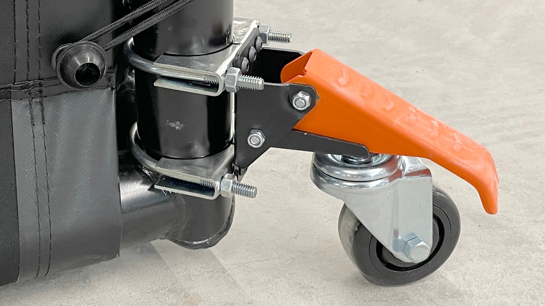
How-To, PRO Golf Enclosures
Moving Your Golf Simulator - How To Add Caster Wheels

How-To, Golf Enclosures
How to Assemble a Curved Golf Enclosure Kit

Resources, Golf Enclosures
Find the Type of Golf Simulator Enclosure That Fits Your Room